Adjusted pushrods (lifters). Engine pau

It's been months since I've last written and worked on my bike; it was a busy end-of-the-summer finishing up other projects on my plate. I am happy to finally be able to give some TLC and attention to my Ironhead.

(There may be gaps between what I last wrote and this post. That is the biggest challenge here--having time to work on the bike AND photo-document each step in the work as it takes more time when a camera is involved. So if you are reading this, I thank you for accompanying me on this journey, gaps and all.)

Today I adjusted the pushrods (the term is "adjusting pushrods" but technically, it is the lifters that are adjusted), which was the final task in buttoning up my motor. The pushrods have an important function in the engine--they open and close the valves, which is part of the engine combustion process.

These four vertical pipe-looking things are the pushrod covers. The pushrods are housed in the tubular steel covers you see here. Inside the covers are the pushrods which connect to lifters, which are at the bottom of the pushrods and sit above the cams (the cams engage a wheel at the bottom of the lifter, which make the pushrod go up and down).

IMG_0188 edited resized.jpg

Again, cutting-edge toolery holding up the pushrod cover--you can see the pushrod here. The lifter, at the bottom of the pushrod, is what needs to be adjusted. The motor must be turned until the lifter is at the lowest position. First the lifter bolt is loosened so the pushrod has a lot of play. To adjust the pushrod the lifter bolt is tightened enough so that the pushrod has no up and down play and spins freely, completely around. Sounds easy enough?! And sure, sweaty forehead and armpits and numb fingers later, all of them have been adjusted.

IMG_0182 edited resized.jpg

Then, the pushrod cover spring retainer is put back by simultaneously pushing down on the pushrod cover and pushing in on the spring retainer.

IMG_0191 edited resized.jpg

One down--

IMG_0192 edited resized.jpg

And another one--

IMG_0195 edited resized.jpg

And there you have it. Engine is pau. (For those of you not familiar with the word 'pau')

IMG_0196 edited resized.jpg

Installing cylinders and pistons

Yesterday I started putting my motor back together.

Nikola walked me through the steps yesterday with the rear cylinder, and I repeated that today on my own for the front cylinder. BUT while I lubed both cylinder bores, I did not lube either piston so I needed to redo both of them. That was my arm workout for the week--they weigh about 25 pounds each because they're made out of cast iron, and wiggling them on and off a couple of times each took good arm strength. Lubing is essential as part of the engine assembly process. If you forget or fail to lube any part, you're going to have major engine trouble.

Remember these--the cast iron cylinders, which I sanded and painted?

IMG_0579-edited.jpg

Took off the tape, top.

IMG_0584-edited.jpg

Bottom. Took off the old gasket.

IMG_0585-edited.jpg

Scraped off gasket remnants with razor blade.

IMG_0589-edited.jpg

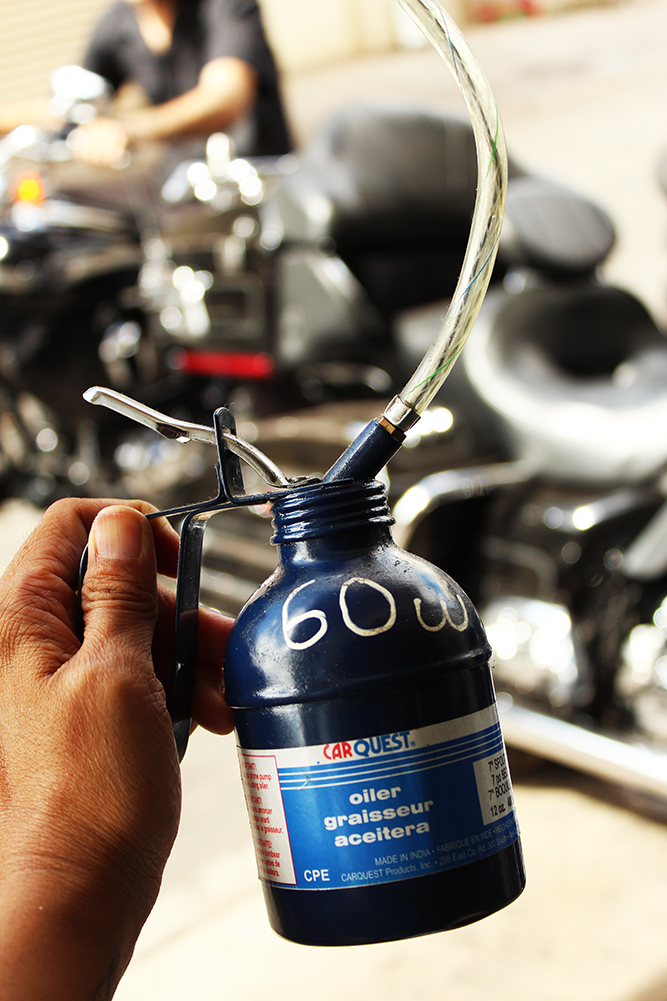
Used 60W oil and a few squares of toilet paper, folded up, to clean and lubricate the inside of the cylinder.

IMG_0601-edited.jpg

Squirted a bit of oil in the cylinder, and started on one side and repeated all around, on top and bottom halves.

IMG_0602-edited.jpg

A diagram of the cylinder components from my service manual.

IMG_0605-edited.jpg

Checked the fit of the gasket on the bottom of the cylinder.

IMG_0609-edited.jpg

Placed the gasket on the cylinder base.

IMG_0611.jpg

Spaced ring gaps about equidistant around piston. Made sure they were staggered otherwise if there were gaps where air could escape, the compression would be low resulting in poor engine performance.

IMG_0606.jpg

Then lubed the piston with extreme pressure, anti-seize engine assembly lube.

IMG_0645-edited.jpg

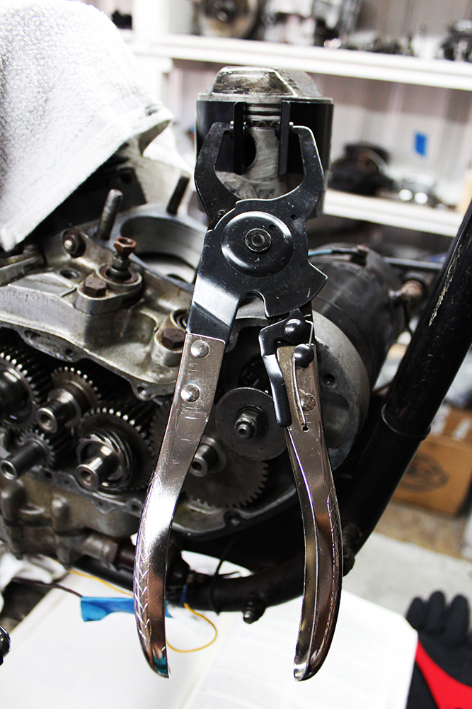
Placed the piston inserter ring tool around the piston and secured with the piston ring compressor.

IMG_0646-edited.jpg

Placed the cylinder over the piston.

IMG_0647-edited.jpg

Used a rubber hammer and alternated tapping the front and back onto the piston. My lovely assistant Nikola held the cylinder and piston up while I tapped.

edited IMG_0617.jpg

Once the cylinder cleared the rings, removed the piston inserter ring and compressor tool and used my hand to pound the top of the cylinder down.

IMG_0623-edited.jpg

Got the sucker on.

IMG_0624-edited.jpg

The top view. The movement of the pistons up and down compresses the air in the cylinder and this is part of the engine combustion process..

IMG_0625-edited.jpg

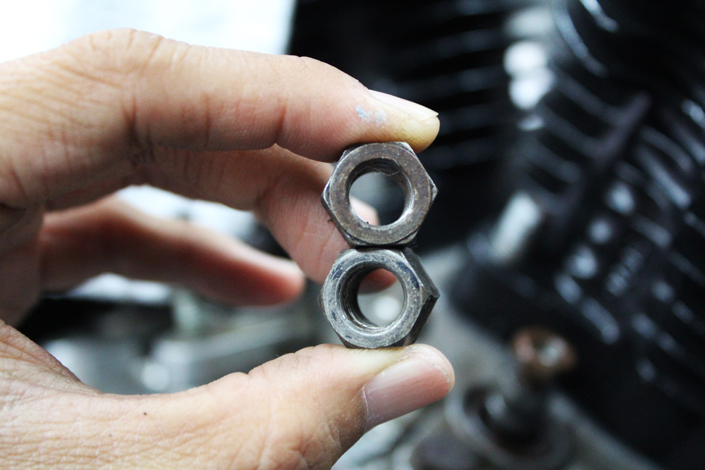
For these old nuts, important to put a bit of this anti-seize lube on the threads so they stay lubed and don't seize up the next time I need to take them off.

IMG_0629-edited.jpg

Just a bit on all of the threads.

IMG_0630-edited.jpg

Then got my nuts.

IMG_0628-edited.jpg

One side is dirtier than the other, which means that side was exposed. The clean side goes down.

IMG_0633-edited.jpg

Tightened each nut to a snug fit with a wrench in a criss cross fashion, so that the weight distributed evenly. The last step was to torque all the nuts to 30 ft lbs.

IMG_0651-edited.jpg

Here's my Buddhi positioning himself in the tight space near my lift to make sure I see his saddest face possible. Promise we'll go to the dog park and beach tomorrow morning, Bud!

IMG_0635-edited.jpg

Sanding and painting II

As I mentioned in the previous post I did a bit of finishing work on the engine in the last few weeks, from 9 thru 13 March 2013.

Here is the cylinder head, taped up for sanding. These were a little difficult to tape up because the engine oil kept seeping from the valve springs. After a bit of Simple Green on the rim, I taped it up then razored off the edges and it stuck.

1973-Mar-2013-1.jpg

The bottom of the cylinder heads: the combustion chamber and intake/exhaust ports taped up.

1973-Mar-2013-2.jpg

Fast forward: heads sanded and painted with high gloss black engine paint

1973-heads-2.jpg
1973-heads-1.jpg

On to the rocker boxes. These are constructed of aluminum. The one on the left I sanded for a few hours, starting with 60 grit (coarse) sandpaper, followed with 150 then 220. Repeated several times. Got the gunk off, but it can still use a lot more sanding with a finer grit paper for more shine. Aluminum can be sanded to a mirror shine using sandpaper and metal polish. This photo tutorial was posted by a guy who polished an aluminum coolant neck (car engine) to a mirror shine; he started with 80grit --> 120 --> 400 --> 2500 and then used a drill with a polishing tool and metal polish. Pretty magical to see the transformation.

Alas, I have much more sanding to do.

1973-Mar-2013-5.jpg

My hands have the same sheen as the silver-painted robot man street performer in Waikīkī on Kalākaua Avenue. Probably should've worn gloves but hard to get the nooks and crannies with those on and my hands always get sweaty.

1973-Mar-2013-6.jpg

In the midst of all of our work, either the motorcycle goddess or a pigeon came and visited our shop and left a feather on the ground for us. The end.

1973-Mar-2013-4.jpg

Sanding and painting I

It's been a month since I've last posted. It is a challenge/juggle to find the time to give to my bike along with all the other day-to-day work and projects that I manage. I now understand Nikola's predicament with his own bike; he literally spends all of his time fixing and giving TLC to his customers' bikes which leaves little time for his Shovel .

On top of this juggling of time, what I've been working on has been a bit more labor intensive and time consuming--

1973-Feb-25-6.jpg

These are the cylinders. They were painted black, and then (I imagine, painstakingly) finished with red paint on each and every cylinder fin. In general my aesthetic is simple and clean, therefore I wasn't digging the red trim. Both the cylinders and the heads, which are constructed of iron, were painted this way and before I could repaint, I had to sand off the black and red paint which took a bit of time. As you may know, sanding and painting aren't one-time deals. They are each a process. When I sanded, I used mostly two grades of sandpaper: 60 and 150 grit. This took several hours. Then I used black engine paint, and I gave each piece two coats of two coats, and they needed to dry completely in between sprayings, so this took me over a week to complete. I started with the cylinders.

This is what the cylinder looks like painted with black engine paint. [Mostly] sanded down to the iron on the left, and new black paint on the right:

1973-Feb-25-2.jpg

Before any of the sanding or painting could commence, I had to tape up all the pukas (holes) so that debris nor paint could get inside, otherwise there'd be trouble in the engine. Taping took a long time too--because of the differently shaped areas and the residual oil neutralizing the adhesive on the tape. Eventually I learned an effective taping method.

Here I am, sanding the black paint off of the heads (which sit above the cylinders and under the rocker boxes) whose pukas I had to make sure were covered with painter's tape.

edited IMG_8378.jpg

Progress!

Progress so far:

progress.jpg